Software Architecture Document for the Body Tracker application
| Author: | Vito Gentile |
|---|
Introduction
Purpose
The main goal of this module is to provide full body tracking of the astronauts, in order to interact with the ERAS virtual station. Using data provided by this module, the avatar of an astronaut can move inside the virtual ERAS station environment, by reproducing body movements of a real user inside a Motivity treadmill.
This module is based on the 3D skeleton tracking technique described at this link. The Microsoft Kinect device generates a depth map in real time, where each pixel represents the distance between the Kinect sensor and the closest object in the scene at that pixel location. Based on this map, the Microsoft API implements the aforementioned skeletal tracking algorithm to accurately track different human body parts in 3D. This technique allows to estimate the position of 20 skeletal joints, which can be used on the Blender game engine to properly animate a 3D avatar model.
Note
This module supports and has been tested with the Xbox 360 version of Microsoft Kinect.
This module supports up to four Kinects simultaneously connected to a single machine.
An algorithm to estimate user steps using skeletal joint data is included in this module, in order to estimate and reproduce navigation paths that an astronaut defines by walking inside a Motivity treadmill.
Previous versions of the skeletal tracking module were implemented in C++ using OpenNI/NITE framework, and then C# using the Microsoft Kinect SDK. The new version of this module is based on PyKinect [2], which allows to use the Microsoft API with Python.
The following flow chart gives a pictorial view of the working steps of the body tracker application.
Figure 1. System architecture. One main server with MS Windows is used to manage up to 4 Kinects. Data from these devices are sent to the Tango bus, that makes them available for any other ERAS software module.
Scope
TBC
Applicable Documents
TBD
Reference Documents
Glossary
IMS- Italian Mars Society
ERAS- European MaRs Analogue Station for Advanced Technologies Integration
V-ERAS- Virtual ERAS
VR- Virtual Reality
TBD- To be defined
TBC- To be confirmed
GUI- Graphical User Interface
For better understanding this document, a clear distinction between different kinds of users that interact with the system is needed.
Astronaut- An user that interacts with the system using different devices and tools, such as Kinect, Oculus Rift, Motivity and so on, in order to explore the virtual Martian environment
Developer- An user that interacts with the system in order to change its behavior. A developer can use programming languages to edit the source code of any ERAS software module
System manager- An user that interacts with the system in order to install and configure it, or to assist and/or monitor an astronaut during his/her interactions with the system
Overview
TBD
Make an overview in which you describe the rest of this document and which chapter is primarily of interest for which reader.
Architectural Requirements
Non-functional requirements
Previous version of skeletal tracking module have been based on open source solutions. However, using the Microsoft API provided with the Kinect SDK v1.8 has shown better performance, so it has been decided to use this software solution.
In order to exploit Microsoft API power, a server with Microsoft Windows 7 is needed. It means that a license for using this operating system is mandatory.
The development process is based on the use of Microsoft Visual Studio 2012 IDE. The Express edition can be used, and it is free (so there is no need for a license).
The application should be written in Python, using PyKinect for interfacing with Microsoft API. It requires CPython 2.7 installed.
Communication among this and other modules is based on the availability of a Tango bus.
Use Case View (functional requirements)
This module should track skeletal joints from an astronaut, and make these data available on the Tango bus.
An algorithm to estimate user step using skeletal joint data should be developed and included in this module, in order to estimate and reproduce navigation paths that an astronaut defines by walking inside a Motivity treadmill.
This module should be able to track hand gestures too.
An usable GUI should be provided, to allow system managers and maintainers to manage multiple Kinects.
Interface Requirements
This section describes how the software interfaces with other software products or users for input or output.
User Interfaces
GUI (Graphical User Interface)
A graphical user interface is provided to system managers, in order to manage multiple Kinects connected to the ERAS system. This GUI can be executed under Windows on a desktop PC, on the same machine that manages skeletal data (the “main server” in Figure 1).
The interface is similar to the one shown in the following pictures:
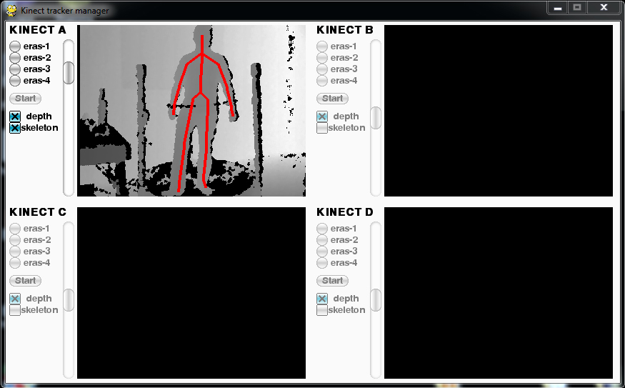
Figure 2. GUI with a single Kinect available, and not yet connected to Tango
Available Kinects are those with labels colored in black, while gray labels are used to visually identify the unactive (or unplugged) devices. When a Kinect is available, a system manager can decide to assign it to a Tango server, by selecting the radio button next to the server name.
When multiple Kinects are available, it is possible to figure out “which Kinect is which”, in the sense that by observing depth images and comparing them with the scenes in front of each Kinects, you can mentally bind the letters used in the GUI to the physical device.
A sliding cursor is also available on the left of each images, to adjust the tilt angle.
CLI (Command Line Interface)
The GUI can be opened by executing:
python gui.py
This will allow a system manager to manage multiple Kinect from a single interface.
For testing purporses it is also possible to start the tracking process by using a single Kinect device. In this case, the command to execute is:
python tracker.py eras-X
where eras-X is the Tango device name (so X can be a value between and
including 1 and 4).
The tracker.py script can also be used for simulation. The following
command allows to record skeletal tracking data, and store them in a JSON
file called test.json:
python tracker.py eras-X --log test.json
The outputted JSON file can be also used to simulate the tracking, without the need to use an actual device. To do this, just execute the following:
python tracker.py eras-X --sim test.json
To sum up how the tracker.py script works, here is the command line usage
for it:
tracker.py {eras-1,eras-2,eras-3,eras-4} [-h] [--log FILENAME | --sim FILENAME]
API (Application Programming Interface)
TBD
Describes the application programming interface, if present. Foreach public interface function, the name, arguments, return values, examples of invocation, and interactions with other functions should be provided. If this package is a library, the functions that the library provides should be described here together with the parameters.
Hardware Interfaces
The system needs/supports the following hardware components:
Up to 4 Microsoft Kinect for Xbox 360 devices
A Kinect Power/USB Adapter for each Kinect device
A modern PC/Laptop with the following minimal hardware configuration:
- 32-bit (x86) or 64-bit (x64) processor
- Dual-core 2.66-GHz or faster processor
- Dedicated USB 2.0 bus for each Kinect
- 2 GB RAM or more
Software Interfaces
TBC
A high level description (from a software point of view) of the software interface if one exists. This section can refer to an ICD (Interface Control Document) that will contain the detail description of this interface.
Communication Interfaces
The skeletal joints and other data tracked by this module are sent to a Tango bus, so the machine that manages all the Kinects must include these capabilities.
Every other module can read skeletal data from the Tango bus. For instance, the Blender Game Engine can use position of skeletal joints to update the pose of a 3D astronaut model. In addition to this, walking speed and and body orientation are provided by this module via the Tango bus, to be used for user/rover navigation in Blender.
Performance Requirements
The system must track astronaut’s skeletal joints in real-time. This allows the user to synchronize its body movements and gestures to what he/she sees and feels.
Logical View
TBD
Describe the architecturally significant logical structure of the system. Think of decomposition in terms of layers and subsystems. Also describe the way in which, in view of the decomposition, Use Cases are technically translated into Use Case Realizations
Layers
TBD
The ERAS software applicationg belong to the heterogeneous Distributed Control System (DCS) domain which can be represented as a layered architecture. This is a very common design pattern used when developing systems that consist of many components across multiple levels of abstraction as in ERAS case. Normally, you should be developing components that belong to the Application layer
Use Case Realizations
TBD
Give examples of the way in which the Use Case Specifications are technically translated into Use Case Realizations, for example, by providing a sequence-diagram.
Deployment View
TBD
Describe the physical network and hardware configurations on which the software will be deployed. This includes at least the various physical nodes (computers, CPUs), the interaction between (sub)systems and the connections between these nodes (bus, LAN, point-to-point, messaging, etc.). Use a deployment diagram.
Development and Test Factors
Hardware Limitations
- Depth camera included in Microsoft Kinect works at no more than 30 frame per second. This limits the speed of an astronaut’s movements: too fast gestures can result in tracking and/or recognition errors
- Microsoft Kinect may not work well outdoor, due to the IR-based technology used by this device: sunlight can interfere with IR rays used by Kinect, and invalidate depth and skeletal data
- Fields of view (see [3]) of multiple Kinect should never intersect, because this can invalidate depth and skeletal data
Software validation and verification
TBD
Give a detail requirements plan for the how the software will be tested and verified.
Planning
The development of this module is divided in the following phases:
- Implementation of a Python tracker based on PyKinect, which can track skeletal joints and send them on the Tango bus
- Implementation of a GUI for system managers, to support simultaneous use of multiple Kinects
- Definition and implementation of an algorithm to estimate user’s step using skeletal joint data, in order to reproduce navigation paths defined by any astronaut walking inside a Motivity treadmill, or using Motigravity
- Integration of touchless gesture recognition [TBD]
Appendix A: Use Case template
TBD
Use Cases drive the whole software process and bind together all the phases from requirements capture to final delivery of the system and maintenance. They are a very effective way of communicating with customers and among team members. Before every discussion always provide the partners with a set of relevant Use Cases.
During meetings, they stimulate focused discussions and help identifying important details. It is important to keep in mind that Use Cases have to describe WHAT the system has to do in response to certain external stimuli and NOT HOW it will do it. The HOW is part of the architecture and of the design.
What follows is the empty template:
Use Case: <Name>
<Short description>
Actors
<List of Actors>
Priority
<Low, Normal, Critical>
Preconditions
<List of preconditions that must be fulfilled>
Basic Course
<Step-by-step description of the basic course>
Alternate Course
<Step-by-step description of the alternate course>
Exception Course
<Step-by-step description of the exception course>
Postconditions
<List of postconditions (if apply)>