Mission Operations Control Center - High Level Design Documentation
| Author: | Mario Tambos |
|---|
Change Record
2015.06.16 - Document created.
Introduction
How to use this document
The objectives of the present document are:
- provide the reader with an overview of how the Mission Operations Control Center is organized,
- facilitate communication between team members by stipulating a common vocabulary,
- aid development and maintenance by specifying and limiting the concerns of each of the Mission Operations Control Center’s components.
This document should be the entry point of any new collaborator to the ERAS project looking to work with the MOCC. From here, such collaborator can choose to continue reading the MOCC‘s implementation, infrastructure or management documents, depending on whether the reader is interested in, respectively, developing software, aiding with the underlying infrastructure or helping with the human resources side of the MOCC. Also relevant for the reader would be the documents specific to the subsystem he/she wants to contribute to.
Purpose
The Mission Operations Control Center (MOCC) is in charge of planning the missions performed in European MaRs Analogue Station for Advanced Technologies Integration (ERAS), and following said plan.
In this context, a plan is understood to be a sequence of activities, together with the expected outcomes of these activities. By following a plan is meant the execution of the plan, the control of its progress as well as the counter-measures needed to correct eventual deviations from the individual activity’s expected outcomes.
Glossary
AI- Artificial Intelligence
ERAS- European Mars Analog Station
EVA- Extra-Vehicular Activity
GUI- Graphic User Interface
IMS- Italian Mars Society
MOCC- Mission Operations Control Center
TBC- To Be confirmed
TBD- To Be Defined
UI- User Interface
Overview
The first section of this document describes at the highest level the organization of the MOCC, its communication channels, subsystems and their general responsibilities, as well as the assumptions made during the design process. The second section describes the documents associated with the present one. Finally, Section 3. deals with miscellaneous factors that need to be addressed or acknowledged when implementing or operating the MOCC.
1. The MOCC System and its Subsystems
High level architecture
The MOCC is divided in five subsystems with clearly separated responsibilities, as shown in Figure 1.
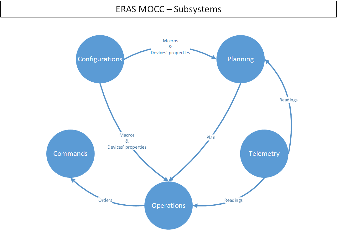
Figure 1. The MOCC architecture
The design’s building blocks are systems, subsystems, components and communication channels.
The MOCC is considered to be a system in itself, which is divided in subsystems. Any external services the MOCC may interface with are also considered systems.
A component is a software artifact that performs certain function. Each subsystem is built of components; no component belongs directly to the MOCC or to more than one subsystem, and there is no part of any subsystem that is not a component.
Finally, communication channels represent all the media and supporting infrastructure needed to allow the exchange of information between the systems, subsystem and components.
The main philosophies behind the design are those of extensibility, separation of concerns, and fault-tolerance: it should be easy to add a new component, it should also be easy to determine where the new component belongs; and, finally, any subsystem should remain functional in the event of failure of all the other subsystems.
Entities
The entities in the The MOCC are classified according to two criteria. The first is whether they are controlled by the MOCC, or if they are outside the MOCC‘s control. Controlled entities are called internal, whereas non-controlled entities are called external.
The second criterion discriminates between so called basic and composite entities. There are four types of basic entities:
- Actors: crew and electromechanical devices able to perform actions.
- Observers: crew and electromechanical devices able to provide information.
- Analysts: AI agents able to deduce information from observations.
- Users: crew operating the MOCC.
On the other hand, composite entities encompass any and all entities that fulfill functions of several basic entities (e.g. actor and observer), for instance:
- Astronauts
- Rovers
- Satellites
- Etc.
Interfaces and Communication Channels
There are four kinds of interfaces to be considered:
- External interfaces, between internal and external entities, or vice-versa.
- Subsystem interfaces, between subsystems.
- Component interfaces, between components of a subsystem.
- User interfaces, between components and users.
Subsystems
The core of the MOCC‘s tasks is performed by two subsystems: the Planning and the Operations subsystems, with the other three subsystems fulfilling support roles.
The Planning Subsystem
One of the two core subsystems of the :MOCC:, the Planning subsystem is in charge of defining the scope and expected results of ERAS‘s missions. The plans this subsystem creates are composed of a series of steps, performed by actor-entities, and parameters. Each step along the way has an expected outcome, which can be checked during the plan’s execution. The plans can be composed of serial steps, parallel steps, or any combination thereof. By parameters is understood any piece of information relevant to the plan’s execution, beside the steps themselves, for instance, the plan’s start date, the plan’s location, or actors involved.
Plans can be one-offs or periodical. In the case of one-off plans a fixed start date is set;M in the case of periodical plans a period is set, e.g., once a day, once every two weeks, etc.
The Planning subsystem comprises two types of components – software and data components. The software components are the user interfaces used to build the plans, together with a set of AI assistants. These assistants should help the user with the plan building, by analyzing feasibility, evaluating constraints, calculating duration and resources, etc. The data components are plan templates, i.e., pre-built plans with free parameters (e.g. no specific resources assigned, or start date set); and plan instantiations, which are plans with all their parameters set.
Figure 2 shows the internal structure of this subsystem. In few words, the person in charge of building ERAS ‘s plans will build plan templates using the user interfaces, with the help of AI assistants. When a plan is needed, this person will then create a plan instantiation, using the same UI and assistants, by filling in the template’s missing parameters. In order to build the templates, the user shall use the information provided by the Configurations Subsystem about the device’s and crew member’s capabilities, as well as the macros. To allow this, the planning UI s must pull this information from the Configurations Subsystem.
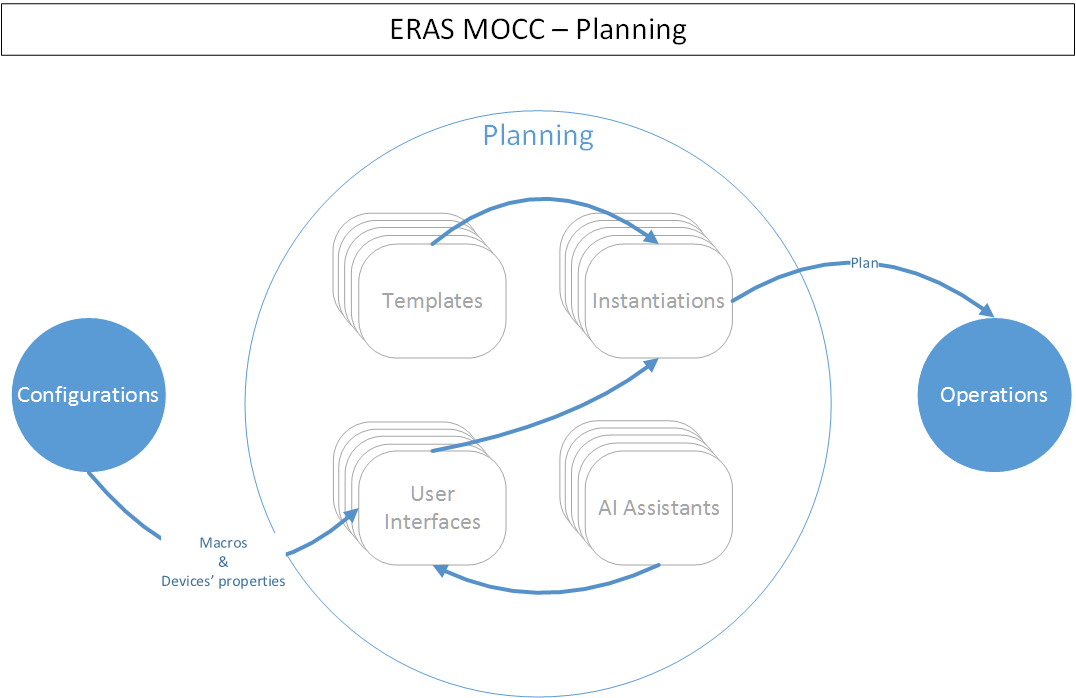
Figure 2. The Planning Subsystem
The Operations Subsystem
This system is the second key component of the MOCC. Its tasks are to execute a mission’s plan, control its progress and correct any eventual deviations from the plan. The Operations Subsystem’s internal structure is shown in Figure 3, whereas the interactions between this subsystem’s components and the other subsystems in the MOCC are shown in Figure 3.1, Figure 3.2, Figure 3.3 and Figure 3.4.
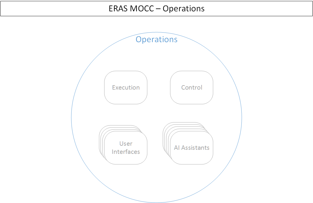
Figure 3. The Operations Subsystem
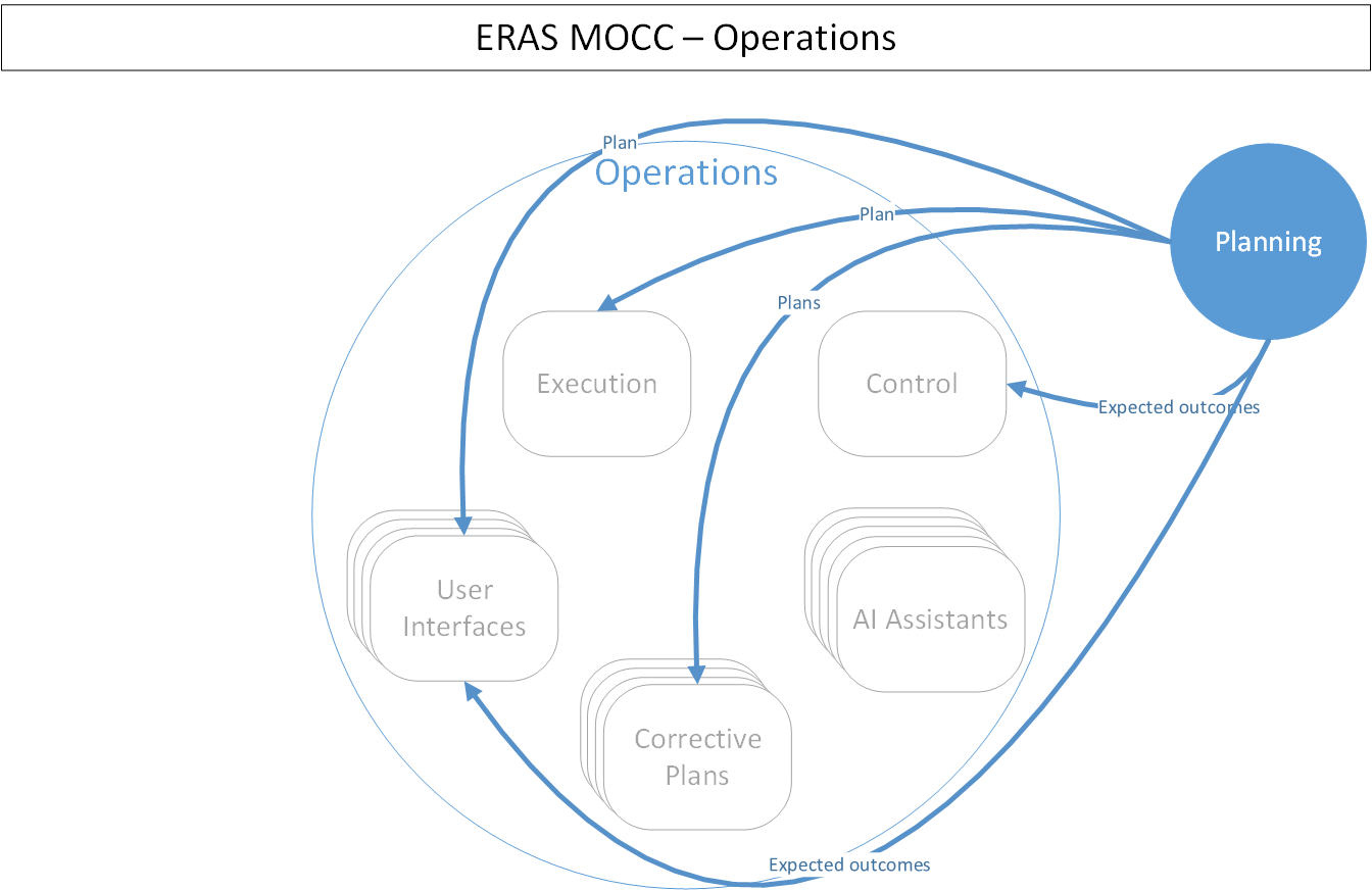
Figure 3.1. Operations interaction with Planning
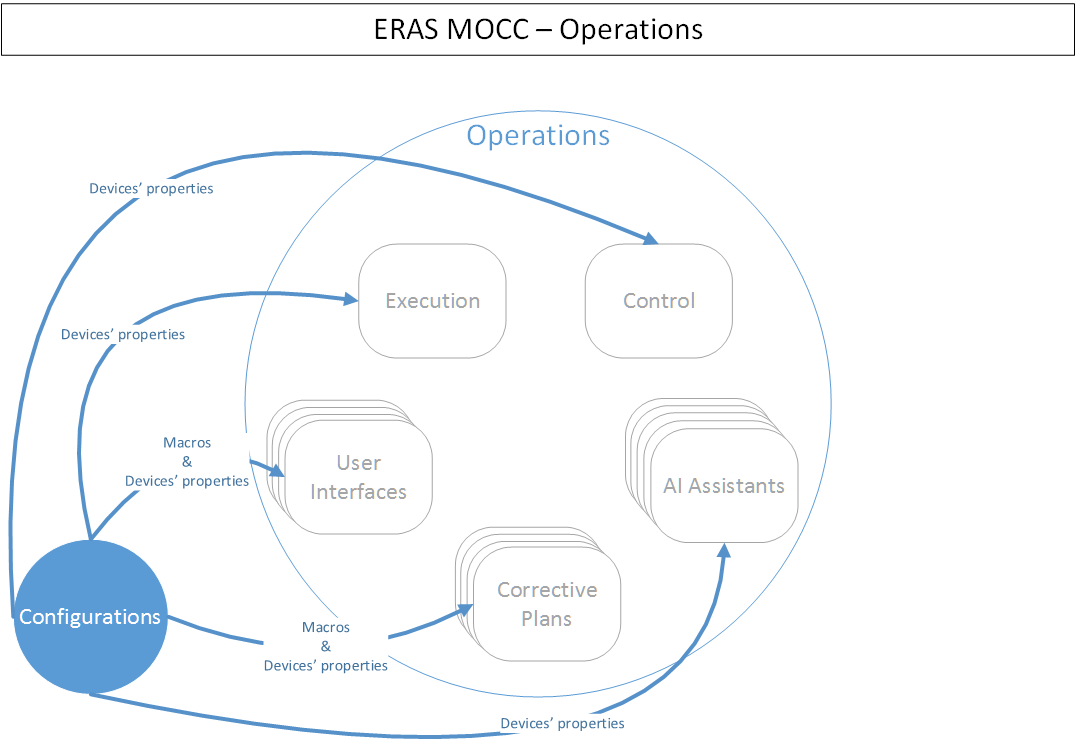
Figure 3.2. Operations interaction with Configurations
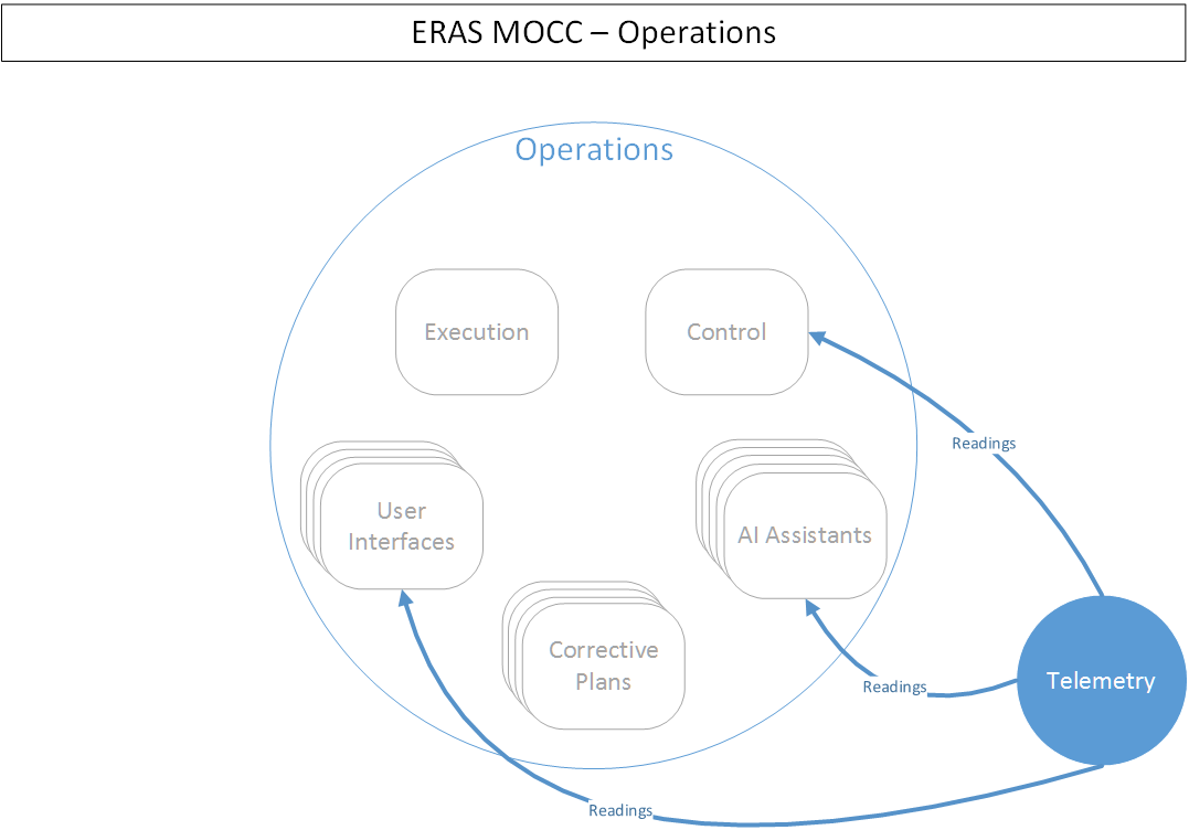
Figure 3.3. Operations interaction with Telemetry
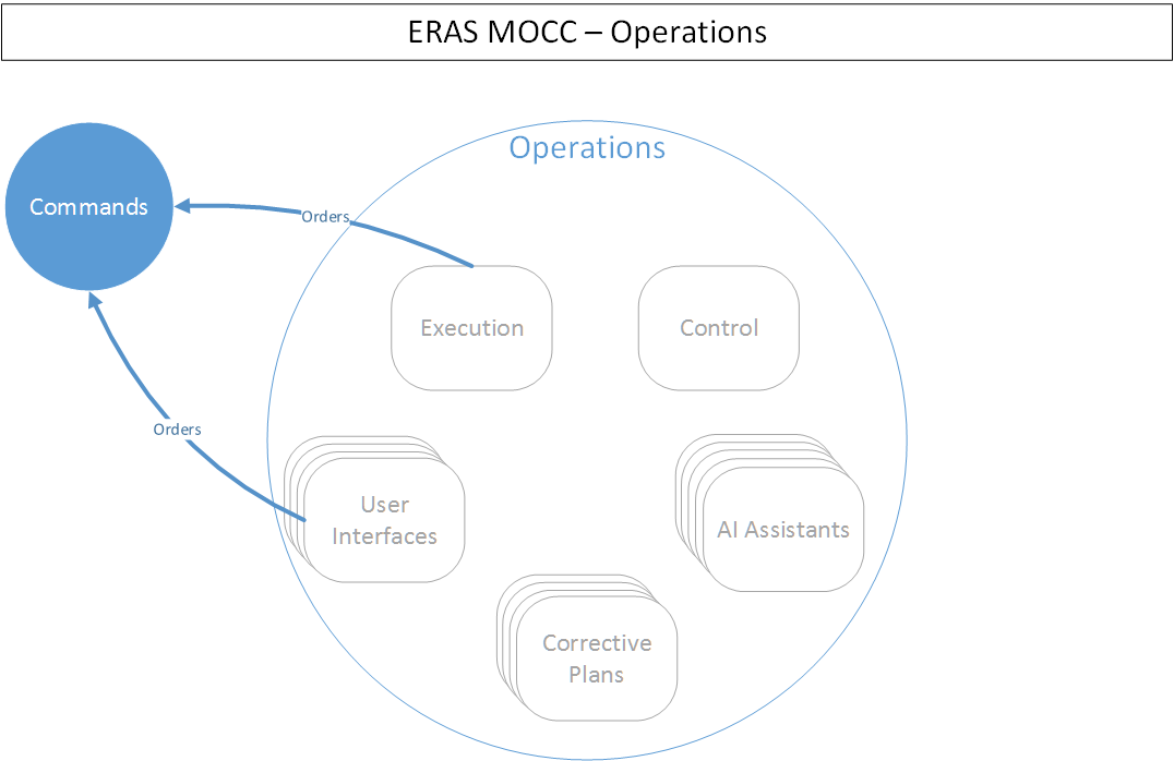
Figure 3.4. Operations interaction with Commands
Executing a plan involves sending commands to devices and crew. Control a plan’s execution involves collecting, analyzing and presenting telemetry from devices and crew to the Operations Subsystem users. Finally, correcting deviations from a plan involves:
- Detecting the deviation, based on the telemetry and the plan’s step’s expected outcomes.
- Devising corrective measures.
- Sending the appropriate corrective commands to devices and/or crew.
The Execution component is in charge of executing the mission plans. This involves sending all automated commands to devices and crew members at the correct time. For commands that cannot be automatically sent, the Execution component should send a cue to one of the UI in order for a user to manually send the command. Part of the Execution component’s task is to pull from the Planning Subsystem information about the next plans to execute. Moreover the Execution component needs to pull from the Configurations Subsystem information about the TANGO device addresses and other interface requirements. Finally, the automated commands are sent though the Commands Subsystem.
The Control component’s task is to check during the plan whether the expected outcomes from the plan in execution match the telemetry readings obtained. If a deviation occurs, the Control component should send an alarm to one of the UI, in order to allow the users to perform the necessary corrections. To carry its tasks, the Control component needs to pull from the Configurations Subsystem information about the TANGO device addresses and other interface requirements. The Control component must obtain the device’s telemetry readings from the Telemetry Subsystem, whereas the plan steps’ expected outcomes come from the Planning Subsystem.
The Operations Subsystem’s user interfaces have four tasks:
- Show the progress of a plan execution.
- Present the user with the telemetry, and their analysis, collected during a plan’s execution.
- Provide the means to send commands outside the plan to the devices and crew.
- Allow the user to build, review and execute corrective measures, in case of a plan deviation.
These UI s get the information about the devices from the Configurations Subsystem. They also interface with the Telemetry Subsystem to obtain telemetry readings, as well as with the Commands Subsystem allow manually sending commands. Finally, the UI s have to interface with the Planning Subsystem to show the plans and the plans’ execution.
The AI assistants in the Operations Subsystem are of two types:
- Telemetry Assistants perform analysis and prediction on subsets of all the telemetry collected. This is used to present summarized information to users, detect problems, project outcomes, etc.
- Corrective Assistants help the users build and execute corrective measures, in case of a plan deviation.
The assistants need to interface with the Configurations Subsystem, to obtain devices’ addresses and other interface requirements, and with the Telemetry Subsystem, to obtain the devices’ readings.
The building of corrective measures mentioned previously can be done by using a plans from a previously built repository of corrective plans. This repository should contain plans for correcting common deviations. One such scenario would be as follows:
- A mission’s plan contain a step to drill rock.
- One of the expected results of the step is that the drill bit’s temperature will rise up to 60°C.
- During operation, the drill bit’s temperature rises to 80°C.
- The user detects the deviation from the expected result (with help from a UI, the Control component and possibly a AI assistant).
- To correct the deviation, the user selects a corrective plan for overheating drill bits from the repository, fills the needed parameters, and executes it.
These corrective plans should be built based on both the devices’ and crew members’ properties, as well as on the original plan.
The Configurations Subsystem
This subsystem is in charge of storing and making available information about the devices and crew that can potentially be involved in a mission, as well as macros. A macro is understood to be a series of steps performed by an actor. The steps in the macro have no expected outcome, however, the whole macro does. Macros differ from plans in that macros have neither a start date. The function of the macros is twofold:
- Help the user build plans and corrective plans by providing a repository of common steps.
- Encapsulate the details of the devices.
The Configurations Subsystem’s internal structure is shown in Figure 4.
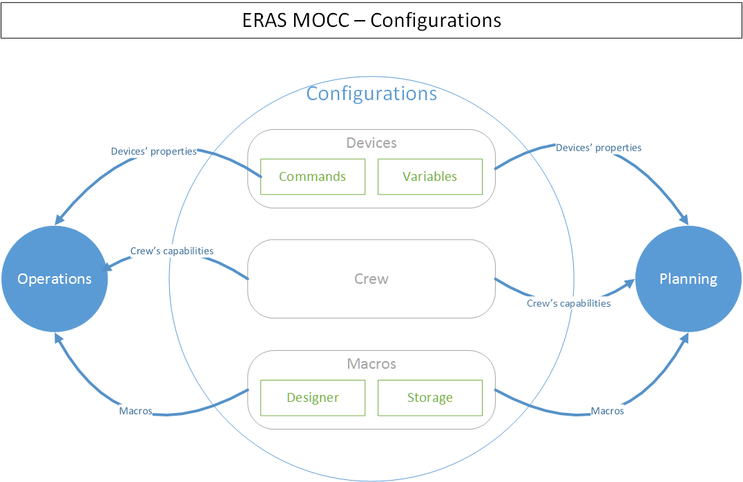
Figure 4. The Configurations Subsystem
Therefore a macro is a higher level interface to the devices. For instance, consider a situation where a user needs to setup an RF chain to receive satellite telemetry. Without macros, the plan should include steps for setting up every device in the chain, with the consequent need to know of the details of those devices. With macros, the user could request an RF setup-macro and use that instead, without having to have knowledge of how the devices in the chain need to be setup.
The Configurations Subsystem comprises three components:
- The Devices component stores and provides information about the commands a device can receive and how those commands must be sent: channel the command must be sent through, input parameter’s types and restrictions, etc. This component also handles information about the telemetry a device is able to provide, in the form of a device’s variables. This comprises how to obtain these variables, and what format they have.
- The Crew component stores and provides information about the crew member’s mission capabilities, e.g., crew member A can perform geological analysis, crew member B can perform mechanical repairs, crew member C can perform first aid, etc.
- Finally, the Macros component handles the design, storage and
availability of macros. This component contains two subcomponents:
- A Designer, which is a UI that allows user to build macros.
- A Storage subcomponent, which saves and makes available the macros in existence.
The Telemetry and Commands Subsystems
These subsystems are in charge of obtaining data from and delivering commands to devices, respectively. Both have a similar internal structure, shown in Figure 5 and Figure 6.
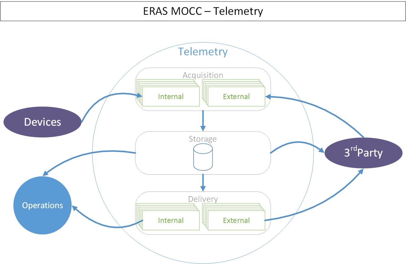
Figure 5. The Telemetry Subsystem
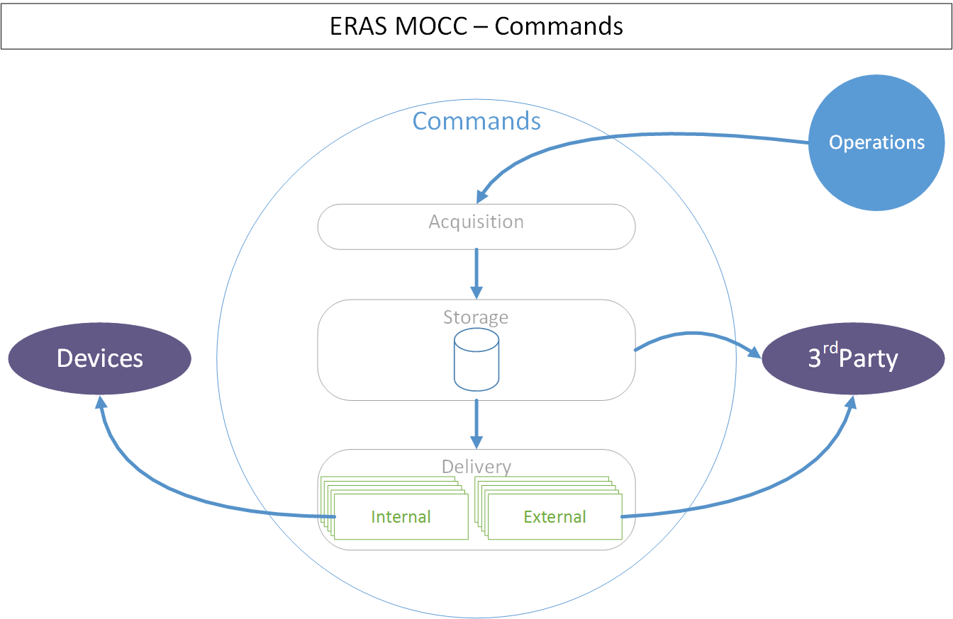
Figure 6. The Commands Subsystem
Both subsystems have three components:
- Acquisition, which obtains data from devices, in the case of the Telemetry subsystem, and commands from other subsystems, in the case of the Commands subsystem.
- Storage, which keeps a historical record of the telemetry read and commands sent.
- Delivery, which sends commands to devices and crew, in the case of the Commands subsystem, and sends data to other subsystems, in the case of the Telemetry subsystem.
These subsystems differentiate between two kind of clients. Internal clients are other subsystem in the MOCC, whereas external clients are those outside the MOCC.
2. Documents
The high level documentation of the MOCC System comprises 10 documents. Five of those cover the whole system:
- The present document, which gives an overview of all aspects of the whole system.
- The MOCC Implementation Document.
- The MOCC Infrastructure Document.
- The MOCC Management Document.
System-wide restrictions on software, infrastructure or human resources should go in these documents.
The other five deal with each subsystem:
- The Planning Subsystem Design Document.
- The Operations Subsystem Design Document.
- The Configurations Subsystem Design Document.
- The Telemetry Subsystem Design Document.
- The Commands Subsystem Design Document.
These last five documents expand on each aspect of the general documents, explaining vague points and refining the granularity of the system-level design. Subsystem-specific restrictions on software, infrastructure or human resources should go in their corresponding subsystem document.